Friday, March 18, 2011

Spud Gun

Spud Gun
An overview of how to make it
The spud gun was constructed of the following:
Barrel: 2" pvc pipe 5'4" long
Piece connecting barrel and chamber: 4" to 2" abs reducer
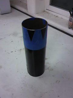
Chamber: 4" abs pipe 2' long
(The chamber was made of cellular core abs pipe, which is not the ideal material to use because it is not pressure rated. It depends who you ask as to if cellular core is safe to use or not for this purpose. You should ideally use pressure rated solid abs pipe, or pressure rated sch 40 4" pvc pipe.)
End Piece: 4" abs female adapter hub
(it fits on the outside of the chamber, and has threading inside which accepts the plug)
Far End Piece: 4" abs plug
This is the spud gun modeled in SolidWorks
You should glue abs to abs parts with abs glue, pvc to pvc parts with pvc glue, and abs to pvc with some sort of general purpose glue. I used pvc glue to hold the barrel to the abs reducer, and it has worked fine so far.

Ignition:
I took apart a lighter for the ignition source. There is a box piece with two pieces of wire coming out of it, which generates a spark. I drilled two holes at an angle in the combustion chamber, and put screws facing in towards each other for the spark gap. I then connected a wire to each screw, and glued the sparker to the side of the chamber. As you can see, I made a mess with the glue.
The gap between the screws is probably around 1/8". It will go off with a couple of clicks.
This is how the screws are oriented inside of the chamber. The red arrows are pointing at the screws.

The furthest the gun has shot is around 240 yards so far, using butane as a fuel source.
This is inherently dangerous, and should be done at your own risk.

Saturday, June 19, 2010

Liquid rocket engine

Liquid rocket engine:

Under Construction

Fuel: gasoline
Oxidizer: gaseous oxygen @ ??? psi
Injectors: dirt bike jet for gasoline, four 1/8" convergent injectors for oxygen, intended to make a gasoline-oxygen mist
Nozzle: mild steel (maybe liquid cooled?)
Chamber: approx 3.5" diameter
Thrust: not yet tested


Injectors: The gasoline and oxygen come into contact about 1/4" from the gasoline jet. The oxygen injectors are drilled at a 45 degree angle, facing towards the center of the plate.

This is a picture of drilling one of the oxygen injectors. When you try to drill at a 45 degree angle, the bit just bends, so I had to make a small piece which holds the bit 45 degrees in respect to the plate.
Construction of the nozzle:

Marking where to cut
A plasma cutter is used to cut along the lines.


This is what it looks like after it has been cut, but before it has been bent.

This is what it looks like after it has been bent

This is after it has been welded together

The "flange" at the top was made in an unconventional manner. Blocks with holes drilled in them were individually welded to the chamber. It is very difficult to align them properly, so they deviate by about 1/20". Two of them deviated by 1/20" adds up to 1/10", so the top only aligns one way (this is very irritating). The gaps were welded in, and the weld beads were ground off. A gasket will be used to seal the chamber to the top plate (which houses the injectors).

This is the engine with the fuel tank (black tank), and the oxygen hoses connected. The fuel tank is positioned vertically, and the fuel is pressurized by some sort of gas (I have used the fuel tank for other purposes, and compressed air works just fine). A ball valve is used just below the fuel tank to shut off the flow of fuel. A spring loaded check valve is used so nothing can get back into the fuel tank. A 1/2" female connector is welded to the top of the injector plate for the fuel to flow. Four 1/4" male connectors are welded to the top of the injector plate for the oxygen injectors. I have not yet decided how to open the valves. Also, I have not decided what pressure to run the oxygen/fuel lines at. I may have to replace the oxygen hoses with ones rated at a higher pressure to give the proper oxygen/fuel mixture.

Hybrid Rocket Engine

Hybrid rocket engine first testings

Fuel: paraffin (sometimes charcoal)
Oxidizer: gaseous oxygen @ 100psi
Injector: 1/2" hole (flow is limited to what can travel through the 1/4" fittings)
Nozzle: 1/8" mild steel, concrete with mild steel insert
Chamber: approx 3.5" diameter
Thrust: not much

The first nozzle was made with six flat pieces of 1/8" mild steel for the convergent - divergent sections of the nozzle, and with a 1" inside diameter ring for the throat. To seal the nozzle to the chamber, a metal ring that fit the inside of the chamber was used.

This is a side view of the nozzle. The piece that holds the nozzle into place is shown above the nozzle.
This is a back view of the nozzle and chamber. The white stuff on the right is the paraffin. In later tests, I reduced the size of the hole, but this did not seem to have much of an effect on the performance.
This is the nozzle after the firing. the hole is about 1" across, and 1/2" high. The hole was on the convergent section of the nozzle. It may have melted down here because of a small hole where a weld ended. The next nozzle is made of concrete, with a steel insert.

Due to inconsistent ignition, a chunk of the convergent section of the nozzle blew out. The high pressure and fast exhaust velocities took out a large amount of concrete from the divergent sections. The nozzle was fitted into the chamber by pressure, but gases still escaped. The metal insert did not show any signs of wear afterwards.


This is the new nozzle setup. It is the salvaged metal nozzle with concrete poured around it. The idea behind this is that the concrete may sync some of the heat from the nozzle, and prevent gas leaks from quickly burning large holes. To seal the nozzle to the chamber, high temperature gasket material was used. This time, the oxygen will be injected by four 1/16" divergent injectors at the oxygen bottle pressure (2000 psi).


To inject the oxygen at these pressures, high pressure fittings are used. The valve is good to 7,250 psi, and cost $27, and the hose is good to 5,000 psi, and cost around $15. The valve has been spring loaded shut, and a rope is pulled to open it. Because of how loud the 100psi tests were, and the 6 foot flame that they shot out, this will be tested in the desert, rather than my backyard. They have not yet been tested.